PCBs for this project have now been discontinued
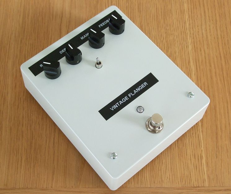
The prototype unit built into a prepainted grey Hammond 1590XXLG die cast aluminium case with simple Dymo lettering.
Requires a Reticon SAD1024 or SAD512D bucket brigade delay chip.
The Oakley Vintage Flanger is based upon the classic big box BF-1 flanger from Boss. I have made some changes including improvements to the power supply, the ability to take a SAD512D or SAD1024, true bypass when off, and adding a switch to allow to choose between negative or positive feedback. Other than that, the circuit design is a 'warts and all' clone of the original schematic. Unlike the original design the PCB is a four layer design utilising separate 0V and +V power planes. The two remaining layers being for signal tracking.
This printed circuit board was originally designed as a test circuit for reclaimed and new old stock (NOS) SAD512D and SAD1024 BBD chips. A flanger makes an ideal test circuit for BBDs since it is easy to hear when something is not quite right. Since I had gone to the effort of making a PCB design for the unit it made sense to make the PCB available to others if they too had spare Reticon BBD chips.
The original BF-1 used a SAD1024 and this is the preferred part for this project if you intend to use your pedal as a flanger and not just a test circuit for BBDs.
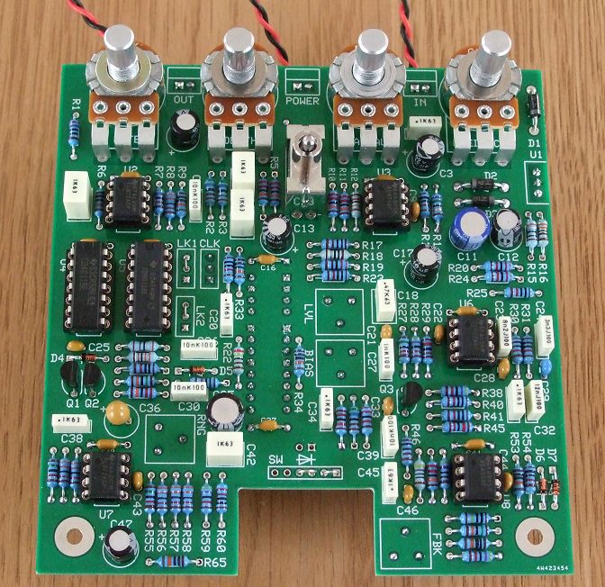
The four layer PCB is 109 mm x 114 mm and will fit into a standard Hammond 1590XX die cast enclosure of size 145 mm x 121 mm x 39 mm. There is a cut out in the PCB to allow for a standard 3PDT footswitch which provides true bypass when off and also illuminates an LED when on. The photographs on this page show the prototype issue 1 printed circuit board. Issue 1.1 PCBs are similar but feature improved component markings.
Power required is 15V to 18V DC with a current consumption of around 50mA.
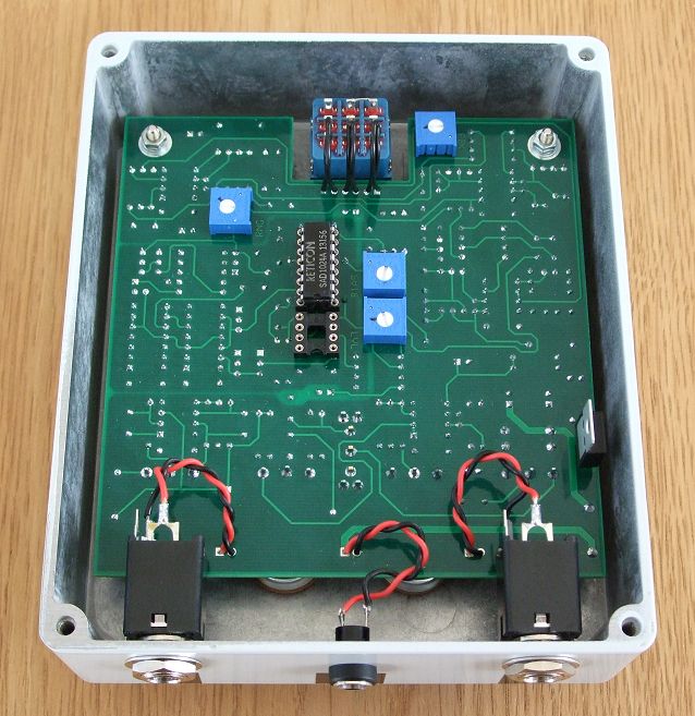
The BBD chip is mounted to the underside of the board for easy removal. Likewise the trimmers are fitted to the underside so they can be adjusted without dropping the board out of the case. This is the prototype board, the current issue 1.1 PCBs have improved labelling.
Project Downloads
Vintage Flanger Builder's Guide
Construction Guide Our handy guide to building Oakley DIY projects
Parts Guide Our handy guide to buying parts for Oakley DIY projects.
Please note a drill template for the front panel is not available at the moment.
Schematics are only available to purchasers of the PCB and will be sent via e-mail when the board(s) are shipped.
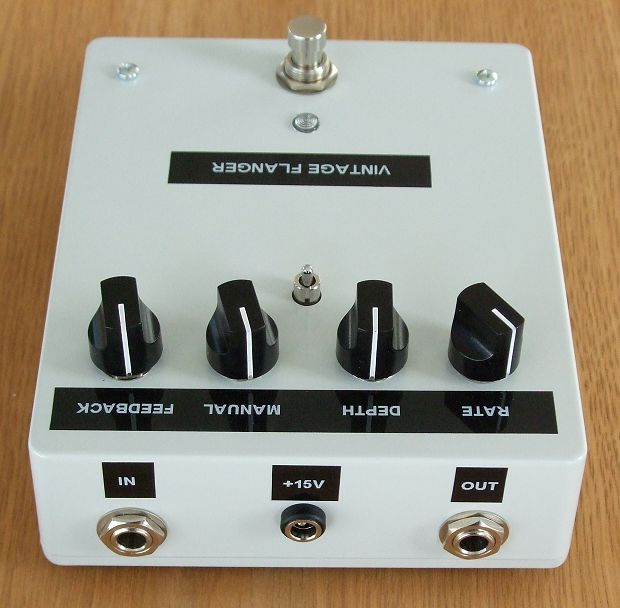
The rear panel of the pedal showing the two 1/4" jack sockets and power inlet.
Back Home