PCBs for this module are now discontinued
A completed MU Dizzy module with integral 5V regulator. The regulator IC has been mounted onto the metal panel to allow currents up to 250mA to be taken from the +5V rail.
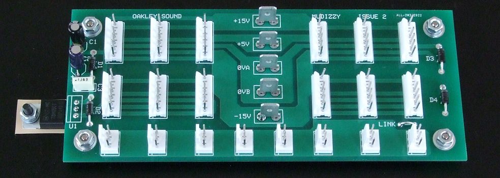
This is a MU power distribution board supporting twelve 5-way 0.1" MTA/Molex headers and up to five 1/4" (6.35mm) Faston blade terminals for power entry. An optional +5V regulator can be built on the board to create a stable +5V 250mA supply from the +15V supply if the main power supply has no +5V available.
Also included in the design are eight 0.1" headers that can be fitted to connect to the Oakley Bus. The Oakley Bus can carry Key CV and gate signals to suitably equipped modules, like the Oakley VCO, VRG, ADSR, etc.
The double sided circuit board is 5.6" (142mm) long by 2.35" (60mm) wide. It is designed to go at the rear of 19" rack units or built into the bottom panel of wooden modular cases. Each row of three headers is 'star wired' back to the blade terminals to ensure to lowest possible resistance and unwanted interaction between connected modules.
It is fully compatible with MU and Oakley/MU power busses.
The Oakley/MU power system is identical to MU power systems except that the normally unused pin 5 position on the MU power header is now connected to 0V allowing both the traditional four way interconnect or a five way interconnect to be used between the module and the distribution board. In all newer Oakley MU modules the module's pin 5 is connected to the front panel and socket sleeve connections which, when used with the MU-Dizzy and five way interconnects, can help in alleviating unwanted inter-module crosstalk.
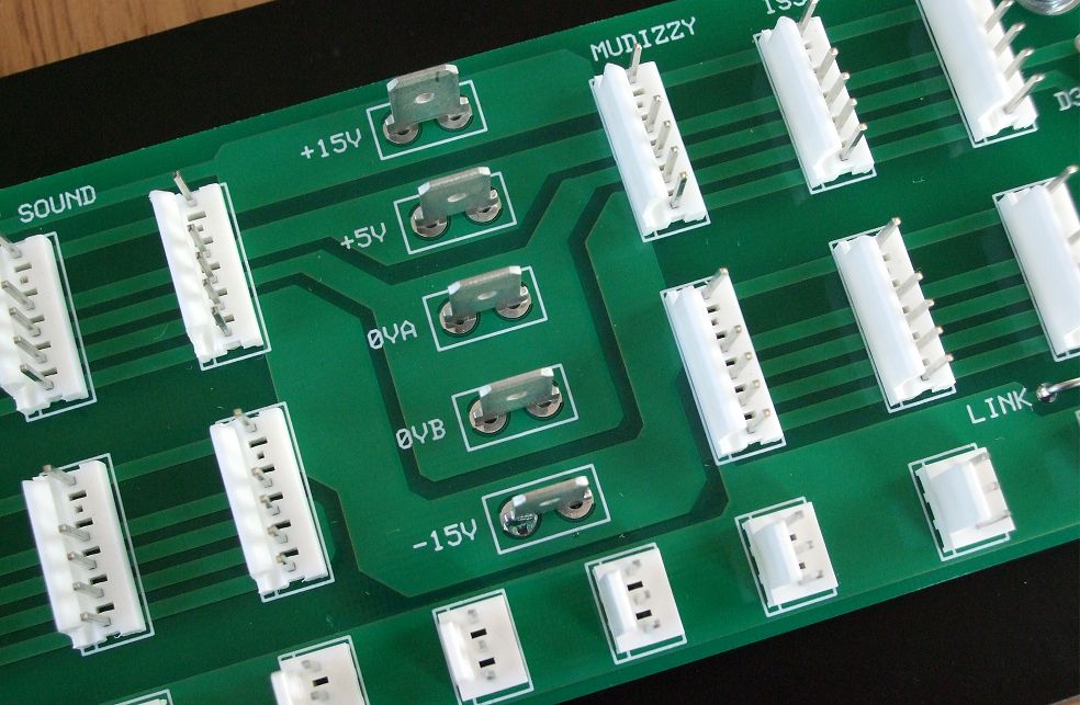
1/4" (6.35mm) Faston blade terminals provide for easy and reliable connections to the master power supply.
Project Downloads
MU Dizzy issue 2 Builder's Guide
Construction Guide Our handy guide to building Oakley DIY projects
Parts Guide Our handy guide to buying parts for Oakley DIY projects
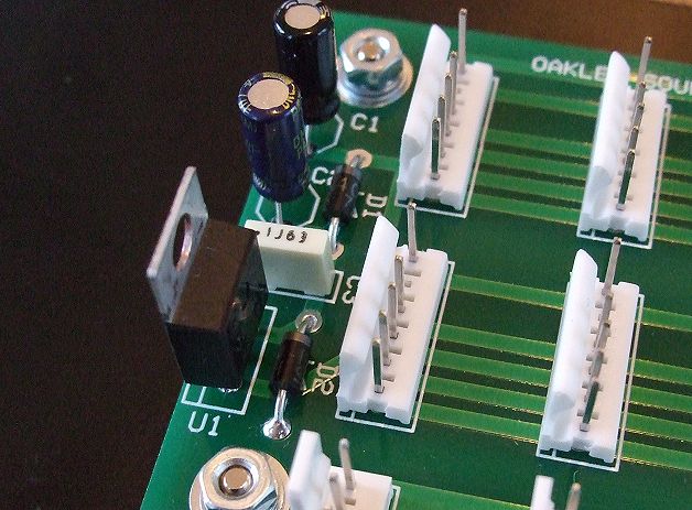
In this build the optional 78M05 regulator is not mounted to the panel and sits above the board's surface. The maximum current that can be drawn from the +5V rail with the regulator mounted in this way is 100mA.
Back home