PCBs for this module are now discontinued
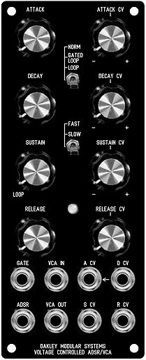
The suggested panel design for the 2U wide complete VC-ADSR module
This is a dual purpose module in a 2U width panel. Not only does it feature a four stage envelope looping generator with full voltage control, but it also has a high quality VCA onboard.
Two outputs are provided, one, labelled ADSR, is the raw output of the core ADSR generator. The other, VCA OUT, is the output of the integral VCA. This highly useful circuit implementation hardwires the ADSR generator to the control input of the VCA. The signal at the VCA's signal input, the VCA IN socket, will then be multiplied by the ADSR waveform. You can use any signal into this input, audio or CV. If you use CV, then the ADSR output level will be governed by the level of the CV. If you use audio, then the ADSR waveform will control the volume of that audio signal.
A typical use would have the IN socket being driven by the velocity CV from a midi-CV convertor. Thus the harder you hit the keys, the greater the ADSR output level. If you use this to control a filter sweep, this can create brilliantly effective touch sensitivity to your patch.
The circuit is configured so that if nothing is plugged into the IN socket, the VCA OUT output will behave the same as the raw ADSR output.
The ADSR is operated by a gate signal, but can also be triggered by slow rising CVs too due to the built in schmitt trigger function. No additional 'trig' input is required.
The VC-ADSR/VCA module is built on two PCBs, one called the VC-ADSR board and the other the Upgrade board. The Upgrade board houses the external CV processing circuitry. Each CV input is controlled by a dedicated pot. This pot acts as a reversible attenuator, so that the gain of the input is anything from -1 to +1. This means that any inputted CVs can subtract or add to the times, or level, set by the ADSR pots. With any input knob set to its middle position then that CV channel is effectively turned off.
Also on this module is an LED. This gives a visual indication of the output level of the internal ADSR waveform.
For DIY builders of this module it is possible to purchase the Sock4 circuit board which is available separately. This little board speeds up the wiring of the four 1/4" sockets and reduces the chances of any wiring errors.
Power (+/-15V) is provided to the board either by our standard Oakley 4-way header or Synthesizers.com header. Current consumption of the Upgrade module is approximately 25mA per rail.
Loop Modes
The Oakley ADSR/VCA incorporates a looping mode. Looping means that the ADSR output will rise to the attack peak at the speed determined by the attack pot and then fall to 0.6V at the speed determined by the Decay pot. It will then rise again to the attack peak and then fall back to 0.6V and so on.
NORM - the module behaves as a standard ADSR.
GATED - the output will loop only when gate is high. As soon as gate arrives the output will rise up at the attack speed and then decay at the decay time and repeat. If the gate is removed at any point the output will then fall at the release time.
LOOP - The module's output it will loop continuously in AD mode. The Gate input has no effect in Loop mode.
In both looping modes the position of the sustain pot can be used to turn the looping on or off. At values above 10% the looping will stop. This is very useful in the 2U version of the module where the looping can be controlled by an external CV.
Please note that the 2U VC-ADSR/VCA module consists of two printed circuit boards, the VC-ADSR circuit board and the Upgrade circuit board. To build the complete 2U module you will need one of each of these PCBs.
Specifications:
Attack times: 0.2 milliseconds to 32 seconds (fast) or 1.6 ms to 250 seconds (slow). Charging voltage +10V, internal attack peak +5V. Pseudo linear ramp.
Decay/Release times: 0.38 ms to 50 s (fast) or 3 ms to 400 seconds (slow). Time measured from 90% of sustain value to 10% of sustain value. Exponential decay slope.
Sustain levels: 0 to 100%
The attack peak and maximum sustain level is 5V from the ADSR socket.
With no jack plug inserted into the IN socket, the attack peak and maximum sustain level is 5V from the VCA OUT socket.
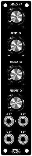
This is the 1U wide 'Upgrade' module required for upgrading the standard 1U ADSR/VCA module. This module would sit alongside the ADSR/VCA module either on the right or left of it.
Upgrade the standard 1U ADSR/VCA module for full voltage control
The standard Oakley single width ADSR/VCA module can be upgraded to full voltage control with an addition of an extra module called the 'ADSR Upgrade module'. This module takes up 1U or 1MU of panel space, and is fitted next to the standard ADSR/VCA to be controlled. The upgrade can be added on at any time and installation is very simple. Two small four way interconnects behind the front panels allow the two boards to 'talk' to each other.
Each of the four CV inputs is controlled by a dedicated pot. This pot acts as a reversible attenuator, so that the gain of the input is anything from -1 to +1. This means that any inputted CVs can subtract or add to the times, or level, set by the ADSR pots. With any input knob set to its middle position, then that CV channel is effectively turned off.
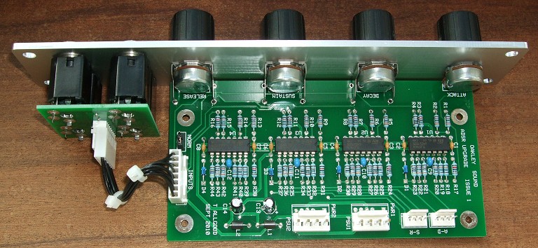
The single width (1U wide) MOTM format module in a natural finish Schaeffer panel. Note the use of the Sock4 socket board to help keep the wiring to the sockets neat and tidy. Note also the two power headers to allow a single power lead to supply both the ADSR module and the Upgrade board. This is an original issue 1 board - issue 2 boards are similar.
Project Downloads
ADSR issue 2 Upgrade Builder's Guide
Construction Guide Our handy guide to building Oakley DIY projects
Parts Guide Our handy guide to buying parts for Oakley DIY projects
If you are building the 2U VC-ADSR module you will also need the ADSR/VCA Builder's Guide found on the ADSR/VCA project webpage.
Schematics are available to purchasers of the PCB and will be sent via e-mail when the board(s) are shipped.
ADSR issue 1 Upgrade Builder's Guide
Front Panel database
A Schaeffer front panel can be made for this module. The databases can be found by downloading the following links:
To read these files you will need a copy of 'Frontplatten designer' from Schaeffer. The program also features on-line ordering, so its now even easier to buy your panels from Scheaffer.
The company are based in Berlin in Germany and will send out panels to anywhere in the world. Delivery to the UK normally takes around ten days. For North American users you can also order your Schaeffer panels from Front Panel Express.
Back Home: Oakley Sound